Design and engineering

Traditional two-dimensional computer aided design (CAD) drawings, along with 3D renderings, were used to create the concept drawings. It is highly recommended to use 3D renderings for any project with multiple elevations and any type of complicated pool or water feature since most homeowners cannot visualize or associate a flat two-dimensional drawing to what is being proposed and ultimately created.
The use of 3D renderings can also help to successfully illustrate to the project’s associated trades what exactly is being built. Costly errors and construction delays from a lack of understanding of the associated drawings can almost be eliminated. A project will be far more rewarding
and successful if all parties are on the same page.
Once the pool’s concept design had been revised and approved by the client, a soil analysis and geotechnical report was ordered to advise the best practices and preparation required to support the new pool footings and structure. These reports should be carried out for all pool construction projects, especially when dealing with areas that have soil which may have been disturbed from previous excavations—in this case the existing pool.
The presence of groundwater was also a concern with the pool being located in a high water table and close proximity to the river. Oversaturated soil would not be a suitable substrate to support the structure and could cause issues without proper drainage. With the geotechnical reports and pool design concept complete, the project engineers would ultimately create the project’s final working drawings.
With the design nearing completion, Charette diligently chose all material selections and finishing materials, making sure to consult with the pool contractor and seek out their knowledge and advice as to what materials would lend themselves appropriately to the design and construction of this project. With the amount of work involved, fluid project management by Charette was a must. Organizing the various trade contractors, material deliveries, and day-to-day logistics was a great challenge and pushed her skills to the test. This streamlined organization was crucial for all involved due to the fact the homeowner is a successful contractor and entrepreneur who is well-respected throughout the community.
Shovel in the ground
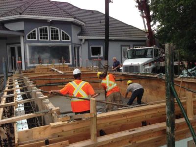
With plans in hand, project materials in order, and all trade contractors selected, the first phase of construction was to demolish the existing pool. With the help of the homeowners own construction crew, the existing pool was quickly demolished followed by a steady flow of limestone aggregate being trucked on-site, placed by loaders and compacted to the stipulations of the geotechnical reports. To raise the entire area and to provide a solid base for the new pool and decking areas, 1,000,000 kg (1000 tonnes) of aggregate were required to fill-in the existing pool excavation. After compacting the fill for several days, strip footings were formed to support the pool walls and landscape retaining walls. The pool was constructed using polystyrene foam forms (ICFs)—an insulated forming system for pools—which are traditionally used in commercial and residential construction.


