Building a knife-edge, perimeter-overflow pool takes precision
by jason_cramp | October 21, 2016 11:45 am
By Michael Willis
 [1]
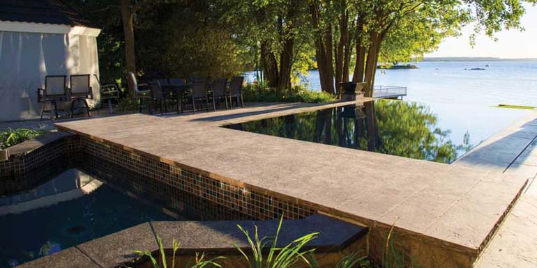
[1]Orchestrated correctly, an infinity pool can create the illusion that a pool and horizon have merged as one. Imagine this scenario: a potential client browses through a project portfolio looking at photos of pools. They view a photo of an infinity pool, but at first glance they do not realize they are actually looking at a pool. This is the ideal result any aquatic designer attempts to achieve when creating these types of pools. Very few watershapes can rival the appearance of an infinity pool and the seamless transition between it and an adjacent body of water. Similar to a vanishing-edge pool, a perimeter-overflow pool takes a design to a whole new level of intrigue and awe, not to mention technical expertise. The complete stillness, reflective qualities, and mirror-like surface result in an appearance that can be breathtaking.
For this particular project located along the shores of the Ottawa/Gatineau River east of Ottawa, Ont., the homeowner was looking to update his existing polymer wall, vinyl-lined pool. Although the homeowners enjoyed their pool, used it daily for swimming exercises, and spent many days/nights entertaining alongside it with family and friends, they were never quite satisfied with its lackluster appearance. In fact, they always felt the existing pool poorly represented their property and the incredible vista overlooking the river and adjacent protected wetlands. Having travelled extensively to resorts and vacationed on properties that featured incredible water vistas which were highlighted by infinity pools and water features, the homeowners wondered if it would be possible to achieve a similar look within their backyard.
To the drawing board
 [2]
[2]This unique and challenging project was brought to the attention of a local design firm, Studio 853 and principal designer Chantale Charette. Her design studio caters to high-end clients with a goal to create a seamless and flowing design—from the interior to the exterior. Following site visits and discussions with the homeowner, as Charette dove deeper into the design phase, she quickly realized the complexity of dealing with a watershape this advanced was above her understanding. If this grand vision was to be a success she needed to bring on-board an experienced contractor/designer who was skilled in intricate custom high-end watershapes.
As a result, she contacted Roger Willis Contracting, an aquatic design/build contractor, also in Ottawa, whom she had collaborated with on previous projects. Their specialty is designing and building unique aquatic projects. The Willis team, together with Charette, took the initial design concept of the pool through numerous revisions. Many elements were added to the overall design, including water and fire features, a covered entertainment space, limestone and granite patios, and ultimately the knife-edge perimeter overflow and vanishing edge. Careful consideration was also taken to create a design that was energy-efficient and sustainable.
The ‘green’ design approach
The chosen construction method for this project was a cast-in-place concrete structure incorporating the use of insulated concrete forms (ICFs). By using this technology, the pool walls would be completely insulated, thus reducing the amount of conductive heat loss through the pool shell to the backfilled areas around the pool. Evaporative heat loss, which is the largest heat loss in a pool, was handled by incorporating an automatic floating slat cover. Further, the cover reduces the fresh water makeup, chemical consumption, and maintenance costs of the pool.
 [3]
[3]An automation system was installed to control all of the backyard elements, including the pool circulation equipment, heaters, lights, and water/fire features. The system has the ability to be remotely controlled by a mobile device such as a smartphone or tablet and the ability for off-site monitoring of the system by a service technician. With the use of variable-speed pumps and automation control, the speed of the pumps can be controlled to minimize energy consumption while still maintaining an adequate turnover rate to recirculate the water through the filtration system. Cartridge filtration was used for its filtering capacity and its lack of need for backwashing, which further reduces overall water wastage. Energy-efficient coloured light-emitting diode (LED) lights were used for their low-voltage requirement and long-life expectancy.
With all infinity pool and perimeter overflow designs, an overflow or surge tank is required. The purpose of this tank is to collect and recirculate the water that passes over the vanishing or overflow edge, as well as collect any rainfall and water from bather displacement. This collection reservoir may be a visible component of the pool such as below the weir wall of a vanishing edge or an underground tank. For this design, the preferred method was to construct a concrete tank adjacent to the pool structure concealed beneath the patio. Since this pool was incorporating a perimeter overflow, the decking surrounding the pool was required to slightly slope towards the water’s edge. This allows for any water that may collect on the deck surface—from splash out or precipitation—to flow into the small gap between the deck surface and collect in the surge tank, where it is chemically treated and recirculated into the system, again reducing the amount of makeup water required.
 [4]
[4]It is common for residential home builders to incorporate green technologies and products into their home designs. That said, the design of pools and spas should be no different, as they are an extension of the home’s interior living space. All pools should be designed to be as energy efficient as possible by means of completely insulating the structure, incorporating an automatic cover, using variable-drive pumps and cartridge filtration, as well as some form of automation control.
The vanishing illusion
An early phase of the pool concept proposed by Charette set the elevation of the new pool at the same elevation as the existing one. In this case, the pool would achieve the vanishing-edge illusion only from the perspective of bathers in the water. From most other vantage points—such as the deck or from the home—the seamless view between the pool and river would be interrupted by a section of grass. That said, the Willis design team was well aware of the importance of establishing the correct elevation for a vanishing-edge watershape. A simple grade error of a few inches could result in a pool not vanishing as intended. When designing or constructing any vanishing-edge project, it is best to discuss with the client the ideal view they wish to obtain and position the pool and elevation accordingly. A few simple questions can save a designer and contractor a world of headache and embarrassment, not to mention the liability or the cost it would entail to modify a failed vanishing-edge project. Therefore, ask the client if the pool should appear to vanish while:
- swimming;
- sitting on a chair on the patio or deck; and/or
- inside the home (sitting, standing, or both?)
By raising this pool’s elevation and re-grading the landscape, it was possible to achieve a seamless transition between the pool and river from all areas inside the house, including the living room, dining room, and entertaining areas.
Design and engineering
 [5]
[5]
Traditional two-dimensional computer aided design (CAD) drawings, along with 3D renderings, were used to create the concept drawings. It is highly recommended to use 3D renderings for any project with multiple elevations and any type of complicated pool or water feature since most homeowners cannot visualize or associate a flat two-dimensional drawing to what is being proposed and ultimately created.
The use of 3D renderings can also help to successfully illustrate to the project’s associated trades what exactly is being built. Costly errors and construction delays from a lack of understanding of the associated drawings can almost be eliminated. A project will be far more rewarding
and successful if all parties are on the same page.
Once the pool’s concept design had been revised and approved by the client, a soil analysis and geotechnical report was ordered to advise the best practices and preparation required to support the new pool footings and structure. These reports should be carried out for all pool construction projects, especially when dealing with areas that have soil which may have been disturbed from previous excavations—in this case the existing pool.
The presence of groundwater was also a concern with the pool being located in a high water table and close proximity to the river. Oversaturated soil would not be a suitable substrate to support the structure and could cause issues without proper drainage. With the geotechnical reports and pool design concept complete, the project engineers would ultimately create the project’s final working drawings.
With the design nearing completion, Charette diligently chose all material selections and finishing materials, making sure to consult with the pool contractor and seek out their knowledge and advice as to what materials would lend themselves appropriately to the design and construction of this project. With the amount of work involved, fluid project management by Charette was a must. Organizing the various trade contractors, material deliveries, and day-to-day logistics was a great challenge and pushed her skills to the test. This streamlined organization was crucial for all involved due to the fact the homeowner is a successful contractor and entrepreneur who is well-respected throughout the community.
Shovel in the ground
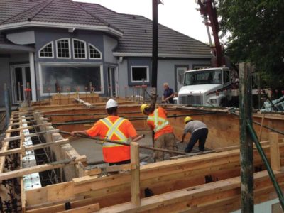
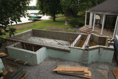
With plans in hand, project materials in order, and all trade contractors selected, the first phase of construction was to demolish the existing pool. With the help of the homeowners own construction crew, the existing pool was quickly demolished followed by a steady flow of limestone aggregate being trucked on-site, placed by loaders and compacted to the stipulations of the geotechnical reports. To raise the entire area and to provide a solid base for the new pool and decking areas, 1,000,000 kg (1000 tonnes) of aggregate were required to fill-in the existing pool excavation. After compacting the fill for several days, strip footings were formed to support the pool walls and landscape retaining walls. The pool was constructed using polystyrene foam forms (ICFs)—an insulated forming system for pools—which are traditionally used in commercial and residential construction.
Insulated concrete form basics
 [6]
[6]ICFs and insulated form technology were first introduced in Europe after the Second World War. The simplicity of construction, labour reductions, energy conservation, and overall structural strength are some of the many strong points of this technology. Initially, the forms were wood units which consisted of a two-sided form with a hollow core to accept poured concrete. With the advent of modern foam plastics, it replaced the wood form sides which greatly increased the insulation value and drastically reduced the weight of the forms. The foam form is held together with an inner tie or web that keeps them aligned and allows placement and attachment of reinforcing steel. The forms are stacked together similar to children’s building blocks. Once assembled, concrete is pumped into the forms using a concrete boom or line pump. While the concrete is curing, another direct benefit of the form’s insulation is the fact the concrete can remain moist during warmer months and insulated during colder months to protect the concrete. Once fully cured, the foam forms remain in place to be used as the final insulation layer of the pool structure.
ICFs for pools
The dual-sided insulation properties of ICFs are ideal for constructing a building or residence; however, there were some issues with regards to using them for installing a pool. The primary concern was how to properly adhere a traditional pool coating to a foam form, while the secondary concern was how the foam would behave behind the coatings. Could the foam sustain the lateral force created during the expansion of pool water during freeze/thaw cycles? Although products are available to be used as a base coat to prime the foam, which usually comprise highly modified polymer adhesives and fibre mesh for reinforcement, Roger Willis and Nudura (a Canadian manufacturer of ICF products) recognized the need for a modified form. The main requirement would be to still use a system that enabled the same efficiency and benefits as the standard ICFs, but would allow the inner face of the form to be removable. This would allow a traditional pool coating to be applied in the same manner used for traditional cast-in-place, shotcrete, or gunite pool construction.
Nudura created a variation of the inner web. The web continues to support the reinforcing steel and align the forms, but attaches only to one side of the standard foam form. Removable forming material such as plywood can be fastened to the interior pool side of the inner web. Once concrete has been placed and sufficiently set, the plywood side of the form can be removed. This alleviates coating the foam form with ‘experimental’ products or stripping of the inner foam to expose the concrete. The pool coating can then be applied directly to the exposed concrete.
It is all in the forming
Forming work for this pool structure was a lengthy process. With the many elements to be constructed, including the pool walls, vanishing-edge, perimeter over flow troughs, surge tank, and automatic cover bunker, careful designing and engineering of the formwork and reinforcing steel was a must. There was zero margin for error since the intention was to pour the concrete for all of these elements at the same time. This allows for a complete monolithic structure providing a near waterproof shell and to maximize overall structural strength and integrity.
The formwork also needed to be constructed with utmost precision to be able to achieve the ideal edge tolerances required (0.79 mm [0.031 in.]) for a perimeter overflow pool. The less the edge tolerance on a watershape of this nature would allow for a lower requirement of hydraulic pumping capacity. This allowed the use of less powerful circulation pumps to achieve the overflow. Ideally, a perimeter overflow pool at static water level with all circulation pumps shut off, should be close to perfect level.
The knife-edge
 [7]
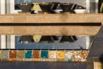
[7]The most challenging aspect during the concrete forming and pouring was creating the ‘Lautner’ knife-edge of the perimeter overflow. This detail originates back to John Lautner, an architect who first used the concept and studied under famed American architect Frank Lloyd Wright.
This detail consists of a pool wall that is sloped away from the water’s edge at a sharp angle (hence the knife-edge), which allows the pool to have no true visible coping. The water overflows the pool wall into a small gap of about 6.35 to 25.4 mm (0.25 to 1 in.) between the decking surface and pool’s edge. The overflowing water is channelled through a perimeter trough or gutter to a holding tank or reservoir, which in turn is recirculated to the pool. The water level achieved is almost flush with the deck surface, giving the pool a unique appearance and highly reflective surface.
This glass-like stillness is achieved since most disturbances within the water are transferred over the pool’s edge as it overflows. The initial application of the concrete during the pouring of the knife-edge is the most critical. The more precision taken during this step would cut numerous hours of preparation time when it came to tiling the edge detail with the selected glass tile. Flamed black-granite stone pavers measuring 609.6 x 914.4 mm (24 to 36 in.) were selected to surround the pool perimeter and cover the overflow trough. Custom steel brackets were required to cantilever and support the granite material. The brackets, resembling a large shelf bracket, were welded on-site to a steel plate that was bolted to the top of the pool trough. The granite stone was cut with a bevel on one side which would sit near flush with the knife-edge leaving a small gap of 12.7 mm (0.5 in.). The stones were adhered to the brackets with a slight slope towards the pool. This would allow any water that may accumulate from wave action or activity in the pool to flow into the perimeter trough.
Full of features
An imported glass tile, manufactured by Lightstreams Glass Tile of California, was selected as the perimeter pool tile, vanishing-edge face, knife-edge tile, step markers and accent tiles for the water and fire features, as well as the covered entertainment area.
This custom blended colour of blue, silver, and bronze tiles are manufactured with an iridescent face which creates a visually stunning array of colours as it reflects light. As the tiles are handcrafted, they commonly suffer from slight imperfections and size irregularities. This proved to be a challenge for the tile setting crews whom placed each tile individually along the vanishing-edge and perimeter-overflow top edge. A combination of rotary laser levels, line lasers, and optical level transits were used to guarantee a precise level of plus/minus 0.79 mm (0.031 in.).
The pool water level itself can sit stationary at perfect level without any means of added recirculation. The concrete pool shell was coated with a water-proofing membrane followed by the glass tile and an application of a thermally applied coating. This coating consists of a colour blend of polymer powder which is pneumatically fed through a nozzle via compressed air, while simultaneously through a heat flame which melts
the powder and adheres to the applied surface.
 [8]
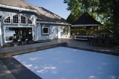
[8]Since the whole project was designed to be energy-efficient, it only made sense to incorporate an automatic cover. As most heat and water loss is caused by evaporation, simply covering the pool can help to lower heating costs by 70 per cent and water fill costs by up to 90 per cent. Sanitation and maintenance costs are also reduced, as less debris enters the pool, while chemical consumption is lowered with the decrease in chemical evaporation. With the knife-edge perimeter overflow, a traditional track automatic cover was not feasible due to the lack of area to mount any tracks to guide the cover. The design team consulted with Tom Dankel of Aquamatic Cover Systems, in California, to help incorporate a cover that would provide the most esthetically pleasing appearance when opened or closed. That said, an automatic floating slat cover was selected. It comprises rigid polyvinyl chloride (PVC) slats which are joined together with a hinge-like connection. The slats are connected to a drive shaft which is driven by a patented hydraulic pump mechanism. This cover is able to retract from a water-filled reservoir adjacent to the pool structure. The slats wind onto the drive shaft as the cover is opened and float to the surface as the cover is closed.
A cantilevered-concrete ‘bridge’ was conceived to separate the pool and water feature, as well as to create a walkway joining the patios on either side of the pool. Not only did the bridge serve as a walkway and divider between the pool and water feature, but also as a way to conceal the floating slat cover bunker.
Custom 304.8- x 1828.8-mm (12- x 72-in.) sandblasted limestone was used as the top face material giving the bridge an illusion of being capped with wide planks of wood. Adjacent to the cover bunker and bridge sits the water feature area. This space shares all the same finishes as the pool, including glass tile, flamed black-granite coping, and sandblasted Eramosa limestone. Raised pedestals were created to support three oil-rubbed copper water bowls with scuppers. These water bowls provide the soothing sound of spilling water, as well as a stunning visual element.
 [9]
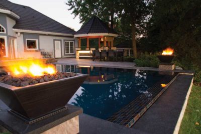
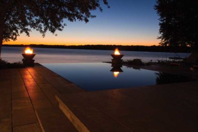
[9]Fire features were located at each side of the pool towards the vanishing edge. The fire bowls are matching replicas of the water bowls. Another standalone fire element is situated adjacent the pool on the deck. This fire feature incorporates a flame and water effect, which flows from a copper bowl with a 360-degree spillway. The decking material surrounding the fire/water element features an intricate circular stone inlay of various stone materials, including flamed black granite, Indian sandstone and sandblasted Eramosa limestone. All stone pavers were cut to fit on-site with each circular banding drawn out from the centre origin of the fire/water element. All remaining deck surfaces and patios, from the two patios adjacent to the pool to the lower patio at the mechanical shed and walkways surrounding the pool area were paved with 304.8- x 609.6-mm (12- x 24-in.) sandblasted Eramosa limestone.
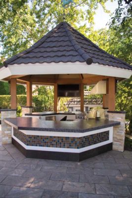
The entertainment area consists of an existing octagonal covered structure which was relocated from another area on the property. The existing structure was a simple post-and-beam building with latticework and a covered roof. The structure was hoisted via extendable man lift to the other side of the property where it was fastened to the new concrete sub-decking. Once in place, the structure was given a complete overhaul, comprising fine carpentry and millwork details for the posts and ceiling, as well as custom fabricated base cabinetry. Imported granite countertops from South America were installed as well as veneer stone capping to define the support posts. Plenty of outdoor kitchen components were incorporated into the structure, including a natural gas barbecue cooktop with side burners and matching range hood, wine and beer fridges, bar sink, and a flat screen television.
With the amount of details integrated within these types of aquatic projects, it is at times difficult to fathom how many pieces of the puzzle have been incorporated to achieve the end result. Praise is needed for the many skilled trade workers, designers, engineers, and associated workers that it takes to create these unique watershapes.
A great photograph may illustrate the beauty of a project, but the amount of passion and effort required is difficult to illustrate. That said, the reason these projects are built with so much attention to detail to give the homeowner a one-of-a-kind view. The ideal result is providing them the opportunity—as the sun sets—to gaze upon their infinity pool and witness that moment where the pool and horizon appear as one.
 [10]Michael Willis is an aquatic designer and partner at Roger Willis Contracting Ltd., an Ottawa-based pool builder specializing in unique, custom aquatic projects. He works in various fields—from project design to completion—and builds throughout eastern Ontario and the Caribbean. Willis is a member of the Master Pools Guild, Pool & Hot Tub Council of Canada (PHTCC), and Landscape Ontario Horticulture Trades Association. He can be reached via e-mail at michael@rogerwilliscontracting.com[11].
- [Image]: http://poolspamarketing.com/wp-content/uploads/2016/10/IMG_0264-cropped.jpg
- [Image]: http://www.poolspas.ca/wp-content/uploads/2016/11/IMG_9739.jpg
- [Image]: http://www.poolspas.ca/wp-content/uploads/2016/10/IMG_0270.jpg
- [Image]: http://www.poolspas.ca/wp-content/uploads/2016/10/IMG_0322.jpg
- [Image]: http://www.poolspas.ca/wp-content/uploads/2016/10/Potvin-Construction1-Pool-Pump.jpg
- [Image]: http://www.poolspas.ca/wp-content/uploads/2016/10/Potvin-Construction4-Pool-shell.jpg
- [Image]: http://www.poolspas.ca/wp-content/uploads/2016/10/IMG_0246.jpg
- [Image]: http://www.poolspas.ca/wp-content/uploads/2016/10/IMG_9733.jpg
- [Image]: http://www.poolspas.ca/wp-content/uploads/2016/10/IMG_0380.jpg
- [Image]: http://poolspamarketing.com/wp-content/uploads/2016/10/Willis_Headshot.jpg
- michael@rogerwilliscontracting.com: mailto:michael@rogerwilliscontracting.com
Source URL: https://www.poolspamarketing.com/trade/building-a-knife-edge-perimeter-overflow-pool-takes-precision/


