

Process
As part of the ‘autopsy’ procedure, Soukup disabled the ignition system, making sure the unit was unable to fire but still able to run the pump. The facility manager verified these symptoms matched what they had been experiencing.
After pressurizing the system, Soukup ensured there were no leaks and the heat exchanger was sound, and then began to prepare the technical data. He knew the active failure points, but needed to identify the passive failure points (i.e. a gas pressure, water flow, or current draw). Soukup took the measurements of the pipe length and fittings, calculated friction loss, and then needed flow rates.
At this stage, it was time for research: reading the manuals, consulting technical papers, and reaching out to factory support reps. Soukup discovered the manufacturer specifications required 681 litres per minute (lpm) (180 gallons per minute [gpm]) of water flow across the face of the heater with closely spaced tees for hydraulic separation. In instances when the heater is installed above the pool’s water line, specifications dictated the primary piping be a minimum of 457 mm (18 in.) above the heat exchanger. This prevents the heat exchanged from draining back when the pumps are deactivated.
As the primary filter pump was being partially bypassed through the heater, it would not be able to achieve the flow rate required. This resulted in flow reduction through the main filter loop.
By calculating the friction loss of the piping at the required flow rate, Soukup was able to size a correct booster pump.
Resurrection
By this point in the assessment, Soukup and his team had gathered enough information to determine the cause of the equipment failure and establish how to resurrect the system.
They developed a plan with multiple stages:
- Rip out the existing primary piping and reinstall the correct size to accept the required flow.
- Install the booster pump in a primary/secondary fashion with hydraulic separation off the main filter loop.
Hydraulic separation was used to de-couple two loops with different flow rates, which achieved two positives: getting a higher flow through the filter, and getting the correct flow across the face of the heater for optimal performance.
Standard procedure requires a replacement of the low water cutoff with a new flow switch on the heater. Upon removing the old flow switch, Soukup found the original equipment installer had stacked four paddles on the actuator—despite the installation’s instructions stating one paddle of the correct size should be installed.
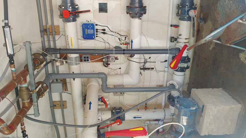
That said, after planning and calculations were complete, Soukup and his team began their job of undoing the mistakes of the previous contractor. All piping and external controls were removed, leaving them with just a heater on the equipment pad and the primary filter loop.
The contractors cut into the main 152-mm (6-in.) filter loop with two closely spaced 76- x 152-mm (3- x 6-in.) tees that would feed the booster pump and provide pump de-coupling.
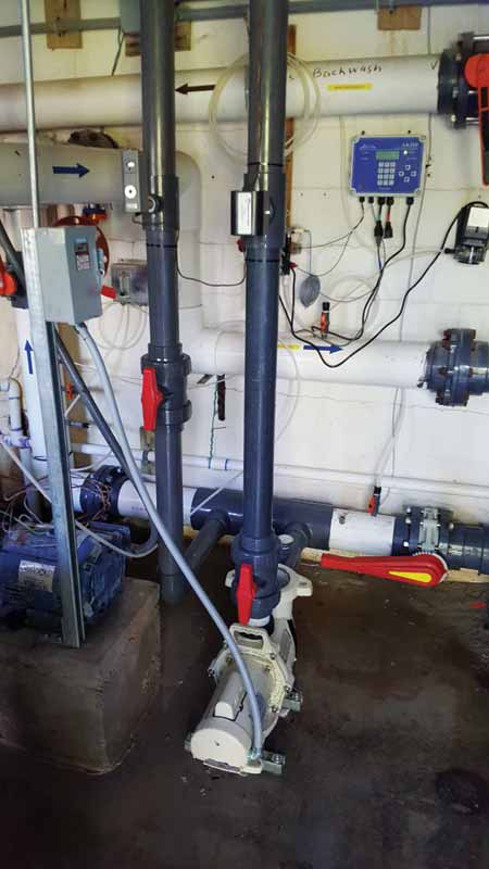
Soukup ran 76-mm schedule 80 polyvinyl chloride (PVC) piping into the booster pump with true union valves for pump service ability. He continued to run these lines with assorted tap tees in place for flow switches and other safety devices.
Then, Soukup core-drilled new holes through the equipment pad under the heater and above the pump room, and continued the 76-mm piping through the pad at a minimum of 457 mm (18 in.) above the pool heater’s heat exchanger. The team then installed a second set of 76- x 63.5-mm (3- x 2.5-in.) closely spaced tees to de-couple the internal heater pump from the booster pump. This allowed a 681-lpm (180-gpm) flow across the face of the heater through the pipe. As per manufacturer specifications, from the tees down to the heater, Soukup and his team installed an H-crossover—which gives the ability to adjust the flow rate of the internal pool heater pump—with valves if temperature blending was necessary. Temperature blending allows for hot and cold water to mix and supplies tempered water into the input side of the boiler to prevent thermal shock and condensing of flue gasses inside the unit. They installed as many unions and valves as possible for ease of future service and usability.


