
Gas heaters are built to last
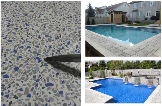
Location, location, location
The proper location of the heater must be determined for new installations or verified for a replacement installation. Care should be taken to choose a location where leakage from the heat exchanger or plumbing connections will not result in damage to adjacent areas or structures.
The heater must be installed so installation and service clearances from combustible surfaces can be maintained per the manufacturers’ specific requirements. Additionally, the heater must be properly installed so its exhaust vent is properly located and spaced relative to adjacent walkways, buildings, opening windows and building openings to comply with the National Fuel Gas Code.
Indoor heater installations are more complex and require specific selection of the appropriate exhaust gas vent sizes and materials. In addition, it must be ensured proper combustion air and ventilation air is adequately supplied to the heater. Consult the specific instructions for indoor installations found in each manufacturer’s installation guidelines and consult local code experts prior to starting any indoor gas heater installation.
Installation sequence
With the heater location now determined and the heater positioned, the installation of the gas line, plumbing connections and electricity can begin. The normal sequence of installation is: gas line connection, plumbing inlet and outlet water connections and high- and low-voltage electrical connections.
When replacing a heater, generally the new heater is simply connected to the existing gas line. However, it is important to understand the key elements, which influenced the original installation to ensure the gas supply is adequate and safe. Each heater manufacturer specifies the proper gas piping size to deliver an adequate supply of gas to the heater, which is dependent on the heater’s Btu size and its distance from the gas source (i.e. a natural gas meter or a propane tank.)
The gas supply connection must include a Canadian Standards Association (CSA)-certified main gas shutoff valve outside the heater cabinet. This shutoff valve must have an inside diameter large enough to supply the proper amount of gas volume to the heater. Subject to local codes, a sediment trap may be required, which comprises a drop-of-pipe off a ‘T-fitting’ to collect impurities in the gas before getting to the heater. It also includes a threaded union outside the heater cabinet allowing the heater to be easily serviced.
Use appropriate soap and water solutions to check the gas connection for leaks and fix even the smallest leak immediately. Do not use an open flame to check for gas leaks, as an explosion can result causing severe injury or death.
Gas-pressure testing is one of the last steps to ensure the proper operation of the burners in the heater. It is performed following connection of the plumbing and field electrical supply. This will be discussed later in this article.
Continuing with the installation sequence, the next area to focus on is the inlet and outlet plumbing connections. Gas pool heaters are typically designed for use with pool and hot tub water only, as furnished by municipal water distribution systems.
Usage with mineral water, seawater (with more than 4,000 parts per million [ppm] of salt) or other non-potable waters will likely void the manufacturer warranty. The plumbing system must also be designed so water flow from the heater return to the pool/hot tub cannot be blocked. (Any blockage could result in fire or explosion causing property damage, personal injury or loss of life).
Today, the vast majority of gas heaters are equipped with chlorinated polyvinyl chloride (CPVC) flanged pipe nipples, union nuts and o-rings (or seals) to ease attachment of inlet and outlet water connections. They also serve to facilitate easy removal of the plumbing connections via the union fittings for winterization or service of the heater. It is recommended to assemble the union fittings and pipe nipples to the heater prior to gluing the fittings to the nipple ends. Today’s heaters do not require heat sinks, heat tapes or fireman switches, which may be present on an older heater being replaced.
With the inlet and outlet plumbing connections in place, it is important to understand proper water flow must be maintained to the heater. Minimum and maximum flow rates are stated in the installation instructions for each manufacture’s specific heater. If the flow rates are not maintained under all operating conditions, heat exchanger damage and/or failure will result and may void the manufacturer warranty. A flow meter, installed on the outlet line of the heater, is recommended to monitor water flow.
Sign up for our newsletter
Get all the latest news and features from Pool & Spa Marketing. Submit your email below to get our twice-monthly newsletter.
Products


Read the Latest Issue