
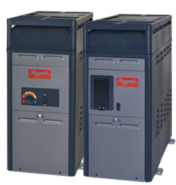
Gas heaters are built to last
Connections

The final necessity is the electrical supply connection. Electronic ignition and electronic ignition fan-assisted heaters all require an electrical connection to operate the electronic control, ignition system components and combustion fan. Most heaters are shipped from the factory wired for use with a 240-volt AC, 60-Hz field power supply, but are capable of being converted for installations requiring 120 VAC, 60 Hz.
To avoid blown fuses and damage to electronic components, which can void manufacturer warranties, verify the field supply voltage and the heater supply voltage are the same prior to wiring. All wiring connections to the heater must be made in accordance with the latest edition of the National Electrical Code ANSI/NFPA 70, unless local code requirements specify otherwise. The heater must be electrically grounded and bonded in accordance with local codes or, in the absence of local codes, ANSI/NFPA 70.
Remote control connection is quite common for regulating water temperature and switching between pool and hot tub modes. These are low-voltage connections made to a terminal block located inside the heater cabinet. These connections should be made in accordance with the manufacturer’s instructions.
Testing
Upon completion of the gas, water and high-and-low voltage electrical connections, an installation check and a general startup is necessary. This is essential to verify all gas, water and electrical connections have been properly made and no leaks, gas supply or water flow issues are present.
Water must be flowing through the heater during operation. Check the pump is operating and the system is filled with water and purged of all air prior to starting the heater.
The gas heater and its gas connection must be leak-tested before placing the heater into operation. The heater must be isolated from the gas supply piping system by closing the manual shutoff valve during any pressure testing. After pressure testing, turn the gas supply on and test all pipe and tubing joints for leaks using a soap and water solution.
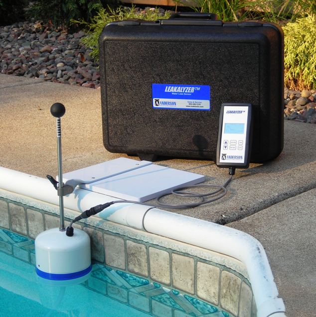
Gas pressure testing ensures the heater’s burners operate properly. Improper gas pressure or gas volume will create a flame, which burns completely yellow, lifts off the burner and generates soot on the heat exchanger.
Gas supply (i.e. the available amount of gas with which the heater is supplied) can be accurately checked on the incoming and manifold side of the heater’s gas valve (with the gas valve on). A manometer will be required to read pressure in inches of water column and all gas pressure verification testing should be conducted per the manufacturer’s specific instructions found in their installation or operating manual(s).
If gas pressure is determined to be inadequate, check for undersized piping between the gas meter and the heater or for a low-capacity gas meter.
Sign up for our newsletter
Get all the latest news and features from Pool & Spa Marketing. Submit your email below to get our twice-monthly newsletter.
Products
Read the Latest Issue