by Sally Bouorm | December 1, 2014 12:56 pm
By Brian Burton
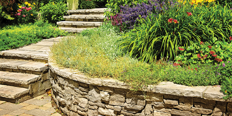
Conventional or gravity segmental retaining walls (SRWs), referring to manufactured retaining walls, as opposed to natural stone walls, effectively limit the movement of the soil behind them, primarily by the weight of their blocks. The maximum wall height of a single-depth wall is typically directly proportional to its weight, width, batter (face slope), soil condition, and site geometry. (Contractors should, in all cases, refer to the manufacturer’s instructions for specific recommendations.) The theory behind these retaining walls is to effectively alter the landscape to increase the area of usable land. On occasion they may be used in cases where there is a very steep or rapid change in the site grading. Retaining walls actually have an extensive history dating back to the introduction of primitive agriculture. These early efforts to improve agricultural production often used readily available local materials to alter the existing natural terrain and drainage patterns.
The basic concept of using the force of gravity and friction resistance based on material shape has been employed in many noteworthy civil engineering and construction projects throughout history with great success. For example, the Egyptian pyramids, most of which are considered to be megalithic structures, were constructed from huge blocks of stone ranging in size from five to 50 tons. Almost all of these structures, which were constructed without mortar, are carefully shaped gravity SRWs. After placement, the blocks or walls were moulded into shape with masonry tools and chisels.
Another example is the Great Wall of China—a raised roadway that stretches for thousands of miles across Asia—which was built by constructing two gravity retaining walls several metres apart. The space in between the walls was later filled with soil and stone to create a roadway. In a similar manner, Hadrians Wall, built by the Romans in AD 122 to “separate Romans from the barbarians,” used the same concept. It involved the construction of a 4.57-m (15-ft) high, 117.5-km (73-mi) long stone-barrier wall across Northern Britain.
Over the past 40 years there have been tremendous changes in the way retaining walls are designed and constructed. The first wet-cast prefab concrete walls were introduced shortly after the end of World War II and were the walls of choice for many years, although timber walls did hold a share of the market. Dry cast segmental concrete block walls were introduced in the ’80s. A few years later, the industry saw the introduction of various plastic components such as geogrids, geomembranes, and geosynthetics, which improved performance and reliability when used in conjunction with retaining wall units.
In more recent times, engineers typically used wooden-timber walls, cast-in-place concrete, and precast concrete panels to construct earth retention systems to provide steep or vertical surfaces. These materials and construction techniques generally contributed to an imposing industrial appearance and, in the case of timber walls, had an expected life span of only 10 to 15 years before replacement was required.
Note: Wooden retaining walls were usually treated with creosote, a poisonous oily liquid obtained from the distillation of coal tar. Crude creosote oil, also called ‘dead oil’ or ‘pitch oil’ has been used as a wood preservative since 1916 for fence posts, hydro poles, railroad ties, etc. The toxic component, polyaromatic hydrocarbon (PAHs), is considered an environmental hazard. On occasion, contractors may be required to remove or dismantle existing wooden retaining walls and as a result, may come in contact with potentially hazardous materials. Although these systems are probably not as environmentally sensitive as when they were originally installed, contractors should still take the necessary steps to limit exposure to creosote. Normally it is considered good practice to limit disruption of the adjacent soil to the greatest degree possible. In addition, based on site conditions, contractors may consider personal protection in the form of gloves or masks. In some cases, the building permit or local municipal regulations may apply or the contractor may wish to inquire with the local authorities. The same may be true for disposal and transportation.
While there are many different methods to constructing retaining walls, the following are the most common.
These older-style retaining walls are typically fabricated from stone or, in some cases, other heavier materials, principally relying on their substantial weight to resist pressures of the adjacent soil. Normally, contractors should build the wall so it is at least 50 per cent as thick as the height of the wall. Modern gravity walls include concrete crib walls, gabions, boulders, and large, precast concrete blocks. Gabions are usually a type of soil strengthening that uses wire-mesh cages into which cut stone is placed that work to reduce internal movement and erosive forces.
Cantilevered walls are made from a relatively thin system of steel-reinforced, cast-in-place concrete or mortared masonry, fixed at one end, usually by way of a cantilever foundation. The wall operates like a beam, in that it converts horizontal pressures from behind the wall into vertical pressures onto the ground. Occasionally, these types of walls are buttressed on the front to improve their stability against heavy loads.
These walls are pinned—both top and bottom—typically with cables, which are anchored in the rock or soil behind it. Anchors are driven into the material and then expanded at the end of the cable, either by mechanical means or by injecting pressurized concrete into the hole. The concrete expands to form a bulb in the soil. The wall may be embedded at the base and tied to a slab at the top.
These systems make use of reinforcing grids to contain and stabilize the slope. The traction-resistant reinforcement elements change the nature of the soil mass and reduce the earth pressure acting on the wall. In mechanically stabilized earth walls, the soil is artificially reinforced with layered horizontal mats or, in some cases, geosynthetic material. These systems, which use tie-backs, geogrids, or anchor systems, require a considerable amount of space to install correctly. With the development of more durable and quickly constructed systems, such as SRWs, traditional building materials, and systems like masonry, timber, and reinforced concrete began to lose their appeal.
The use of retaining walls in general has increased dramatically in recent years as both highway upgrades and the continuing development of commercial and residential properties have demanded improvements in change-in-grade construction techniques.
Urban construction in cities and towns involves considerable challenges as a result of narrow construction envelopes surrounding transportation corridors and property right-of-ways. On a more immediate and practical level, trees and power lines may limit access to the site.
Rapid urbanization and the need to soften vertical landscapes have accelerated the acceptance of SRWs which typically require less space and provide an attractive and esthetically pleasing façade. Gravity SRWs also provide design flexibility, improved performance, and reduced cost. These systems have also been successfully used as an erosion-resistant embankment and slope retention for lakes, rivers, and other hydrological applications.
SRWs have also been used to enable grading of development sites to boundary limits, thus maximizing the usable area. In addition, they have enabled widening and improvement of transportation corridors and storm water channels within existing rights-of-way.
The basic components of SRWs typically comprise the foundation soil, base or footing materials, segmental wall units, retained soil, drainage fill and, in some cases, the geogrid reinforcements. Contractors should, however, consult the manufacturer’s instructions regardless of the system being used. In most cases, these instructions will identify the components and provide basic descriptions, installation instructions, and other recommendations that will ensure proper installation and information regarding recommended maintenance or, in some cases, commissioning.
The following list is representative, however, the components may vary depending on the retaining wall system being employed, the site conditions, and other factors:
The designer of SRWs must consider the site-specific details of the area in which the wall is placed. Parameters include wall geometry, batter, site, soil and water conditions, surcharge loading, and design lifetime. Other selection criteria can include the availability of suitable backfill materials, project economics, and desired esthetics of the completed project. In most cases, the designer or contractor will also rely on relevant reports of soil conditions and recommendations prepared by an independent third-party non-technical consultant.
There are three main stability modes for SRWs. They include: internal, external, and overall stability.
Factors affecting the external stability include the wall’s height, the pressure and forces on the retained soil, and the weight of the wall. Walls can be designed by any conventional method and are normally calculated using limit state design (LSD), also known as load and resistance factor design (LRFD). Limit state is a condition of a structure beyond which it no longer fulfils the relevant design criteria.
Retaining wall installations are critically dependent on the integrity and stability of base materials below the surface. Any disruption or movement of the base will cause deficiencies to quickly appear. These defects generally manifest as heaving or displacement of retaining wall units, which represent a hazard and can be expensive to repair. (Root barriers are normally required for municipal or commercial applications. If the contractor is concerned about proximity of trees, he/she should consult the manufacturer’s instructions.)
In urban areas the growth and development of tree root systems near retaining wall installations can disrupt the base materials and other components in the manner described. In fact, a recent study cited defects directly attributed to tree root growth as the sixth most common cause of premature pavement failure of retaining wall installations. For this reason, root barriers, which prevent the growth of opportunistic tree roots under infrastructure components, are increasingly recognized as essential components of hardscaping installations. Root barriers have proven, over time, to be effective in eliminating deficiencies in new construction and have also been successfully used to retrofit and repair existing installations. Proper detailing and installation of root barriers is required at locations where tree roots intersect with hardscaping components to ensure successful long-term performance.
SRWs have features which make them practical for earth retention projects. The destabilizing pressure of the retained soil mass is nullified by the combined weight of the individual solid concrete blocks when a gravity SRW system is in use. (The SRW approach is generally referred to in the industry as limit equilibrium analysis.) Designers and engineers usually allow for any overlooked or unexpected pressure that may be exerted upon the wall; therefore, the wall must be able to perform above and beyond the requirements of the stability analysis.
Life cycle cost analysis involves a comparative economic assessment of design, material, and construction alternatives to determine the best value for funds invested. This type of analysis reviews the initial installation cost as well as considers other factors such as maintenance, rehabilitation, inflation, interest, and user costs.
[5]Brian Burton is involved with Award Bid Management Services, an innovative multidisciplinary firm which specializes in technical business writing. The firm assists companies interested in selling goods and services to governments and institutions. He can be reached via e-mail at burton@award-bid-management.com[6].
Source URL: https://www.poolspamarketing.com/trade/using-segmental-retaining-walls-in-hardscaping-projects/
Copyright ©2025 Pool & Spa Marketing unless otherwise noted.